Component

Component

A Component is an implementation of certain image processing / analysis algorithms.

Each component alone does not solve a Bioimage Analysis problem.

These problems can be addressed by combining such components into workflows.

Description

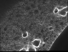
This macro allows to interact with a large, single channel, z-stack (possibly exceeding the main memory of the computer) and to extract a volume of interest by marking several reference points.

has function
The extracted Volume of Interest  (3D rendering)
Description

This macro can stitch a (Z,T,C) data set with virtually no limit on the number of Z slices and time frames. The input to the macro is a folder with the raw tiff images (one image per file) as typically exported by motorized microscopes. These files must all be stores in the same folder and the file naming should ideally comply to OME-TIFF. The macro is however quite flexible: Only --X, --Y and --Z fields with user defined number of digits are compulsory. --T, --C and --L fields with user defined number of digits are necessary for multiple time frames / channels data sets. A compatible data set is provided as a .zip archive. Before processing it unzip it to a given location. The stitching is performed in a reference Z slice (and in a specific reference time frame and channel). The same displacements are applied to all the Z slices, time frames and channels. Before starting the batch processing a montage with the original images of the selected Z slice / time frame / channel is displayed together with the stitched image in this stack. If you are not satisfied with the result you can select another reference. The stitching is then performed time frame by time frame and slice by slice and the stitched images are exported to a single user defined output folder. The macro can also process a data set with multiple channels, the stitching is then computed once on a reference channel and then applied to the other channels.

has topic
has function
Description

This macro builds a stitched image from a muti-position 3D + time hyperstack. The XY positions of the montage should be coded as channels in the input hyperstack. Channel ordering can be configured in the dialog box to adapt to Column/Row and Meander/Comb configurations: The images should appear in this order when browsing the hyperstack with the channel slider. Fine stitching is supported (requires sufficient overlap between the views). The XY displacements of each field of view for stitching are computed for a single reference (Z,T) slice (user configurable) and applied to all slices (Z and T).

Description

Marker-controlled Watershed is an ImageJ/Fiji plugin to segment grayscale images of any type (8, 16 and 32-bit) in 2D and 3D based on the marker-controlled watershed algorithm (Meyer and Beucher, 1990). This algorithm considers the input image as a topographic surface (where higher pixel values mean higher altitude) and simulates its flooding from specific seed points or markers. A common choice for the markers are the local minima of the gradient of the image, but the method works on any specific marker, either selected manually by the user or determined automatically by another algorithm. Marker-controlled Watershed needs at least two images to run: The Input image: a 2D or 3D grayscale image to flood, usually the gradient of an image. The Marker image: an image of the same dimensions as the input containing the seed points or markers as connected regions of voxels, each of them with a different label. They correspond usually to the local minima of the input image, but they can be set arbitrarily. And it can optionally admit a third image: The Mask image: a binary image of the same dimensions as input and marker which can be used to restrict the areas of application of the algorithm. Set to "None" to run the method on the whole input image. Rest of parameters: Calculate dams: select to enable the calculation of watershed lines. Use diagonal connectivity: select to allow the flooding in diagonal directions.

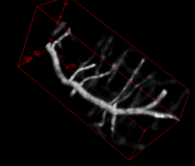
need a thumbnail
Description

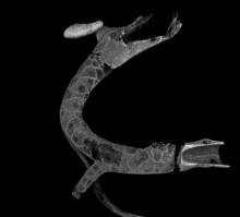
This macro can be used to un-wide a tubular structure and flatten its surface (like peeling of and flattening the skin of a banana). The macro can only process a single channel 3D stack but it is easy to process multiple channels by exporting and importing ROI manager selections. Technically the macro computes the radial average intensity projection inside a ring centred on the radial symmetry axis of the object. The final image is a radial mapping of the intensity (radial angle along X, axial length along Y).

The example image is available in the documentation link. 

has function